
English 
T: +86-13760465505
E: vibetop@163.com
E: vibetop@163.com
No.13, Cheng Guang Industrial park, Dafu Community, GuanLan Street, Longhua District, Shenzhen, GuangDong, China

Views: 0 Author: Site Editor Publish Time: 2026-08-31 Origin: Site


Moving a product from a bare PCBA to a fully housed commercial device presents significant engineering challenges. You must carefully balance thermal performance, environmental protection, and overall manufacturing efficiency. Poor enclosure design often leads to physical assembly interference. It can cause failed IP certification and require highly expensive tooling revisions. These setbacks delay critical product launches and frustrate entire engineering teams. Our primary goal is to provide technical buyers and mechanical engineers a definitive framework. We want to help you execute successful design strategies from day one. This guide ensures you achieve necessary performance targets without over-engineering your mechanical solutions. You will learn how to select the correct alloy for your specific application. We will also explore optimal manufacturing methods and essential design for manufacturability principles. You can then confidently navigate strict environmental compliance standards. This approach prevents unnecessary production inflation and guarantees a highly reliable final assembly.
Selecting the right aluminum alloy (e.g., 6061 vs. 7075) fundamentally dictates machinability, thermal conductivity, and finishing options.
The choice between aluminum extrusion, sheet metal fabrication, and CNC machining hinges on production volume and geometric complexity.
Designing for manufacturability (DFM)—including standardized tolerances and consistent wall thicknesses—reduces scrap rates and accelerates time-to-market.
Stringent environments require proactive design for IP ratings (gasket channels) and EMI/RFI shielding before the first prototype is cut.
Aluminum offers incredible versatility for mechanical engineers. You must evaluate specific application requirements before selecting a final alloy. 6061-T6 remains the undisputed industry standard for general custom aluminum housings. It provides an exceptional balance of corrosion resistance, yield strength, and machinability. This specific alloy accepts protective surface finishes beautifully. It rarely warps during heavy material removal processes. Engineers rely heavily on it for everyday industrial and consumer electronic enclosures.
High-stress environments demand superior mechanical material properties. When designing aluminum aviation parts, engineers frequently turn to 7000-series alloys. The 7075 alloy offers incredible tensile strength comparable to many carbon steels. However, you face specific manufacturing trade-offs here. 7075 carries notably higher raw material costs. It also features lower natural corrosion resistance compared to the 6000-series. You must apply proper anodizing or chemical conversion coatings to protect it from harsh environments.
Thermal management plays a crucial role in modern electronics packaging. Aluminum provides excellent natural thermal conductivity out of the box. This characteristic directly impacts your alloy choice for heat-generating embedded electronics. By leveraging the housing itself as a primary thermal mass, you minimize the need for secondary heat sinks. We often recommend 6061 for its superior thermal properties over 7075 in standard enclosures. A well-designed thermal path draws heat away from internal PCB components efficiently. You ensure stable device operation under heavy processing loads.
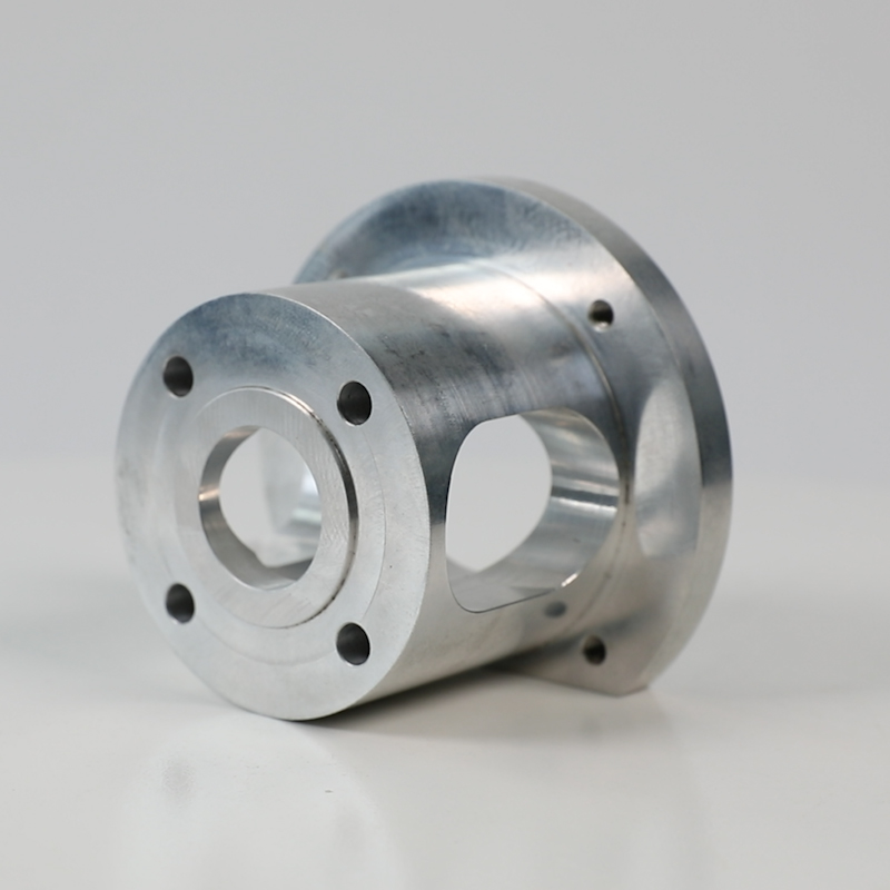
Choosing the correct fabrication method depends entirely on volume and design complexity. We use a straightforward decision framework to guide this crucial choice. You must align your manufacturing process early in the CAD phase.
Extrusion works best for continuous geometric profiles. It excels when scaling up uniform enclosures for mass production. You will incur upfront tooling costs for custom extrusion dies. However, per-unit costs drop significantly at higher production volumes. It suits DIN rail mounts and rugged server chassis perfectly.
Sheet metal fabrication offers a highly cost-effective manufacturing route. It suits low-complexity boxes and simple internal mounting brackets perfectly. The trade-off involves limited structural rigidity and restricted aesthetic options. You cannot achieve variable wall thicknesses using standard sheet metal bending equipment.
CNC machining serves as the ideal choice for complex, monolithic designs. It enables rapid prototyping without any initial tooling investments. Machined enclosures offer superior physical strength and precise dimensional control. They provide maximum environmental sealing capabilities.
Manufacturing Methodology Decision Matrix
Manufacturing Method | Ideal Volume Range | Geometric Complexity | Upfront Tooling Cost |
|---|---|---|---|
Aluminum Extrusion | High (1000+ units) | Low to Medium (Linear profiles) | Moderate to High |
Sheet Metal Fabrication | Low to Medium | Low (Uniform thickness) | Low |
CNC Machining | Low to High | High (Variable thickness, complex pockets) | None (Programmer time only) |
Modern designs often feature highly complex 3D geometries. You must understand exactly when to specify 5-axis aluminum components. This advanced machining process reduces multiple part setups. Fewer setups naturally lower alignment errors across different mating faces. It improves overall positional accuracy dramatically. However, 5-axis machines carry a premium hourly operational rate. You should only specify them when complex undercuts or multi-sided features strictly demand it. Avoid these premium costs if standard 3-axis machines can achieve your geometric requirements through simple flipping operations.
DFM principles directly influence production speed and material scrap rates. Standardizing your internal radii and wall thicknesses remains paramount. You must understand basic tooling realities on the factory floor. Always specify minimum internal radii to match standard end-mill sizes. Sharp internal corners require slow, expensive custom tooling passes or EDM processes. A good rule of thumb suggests an internal corner radius of at least 3mm for typical enclosure depths. Deep pockets require even larger radii to prevent tool chatter and breakage.
Tolerance allocation requires careful engineering constraint management. We strongly warn engineers against using blanket tolerances across entire drawing sets. This common mistake unnecessarily drives up scrap rates and inspection times. Instead, guide your team to specify tight tolerances only where absolutely necessary. Critical mating surfaces or O-ring grooves demand strict dimensional control. You should leave non-critical cosmetic dimensions to standard industry tolerances. Referencing ISO 2768 for general dimensions helps control overall manufacturing costs effectively.
Field assembly relies heavily on proper mechanical hardware integration. You must plan for repeatable and reliable assembly cycles. Direct threading into soft aluminum often leads to stripped holes over time. We recommend incorporating specific hardware solutions:
PEM Nuts: These provide strong, reusable steel threads in thinner sheet metal sections. They press easily into prepunched holes.
Threaded Inserts (Helicoils): They prevent thread galling in machined aluminum during repeated field maintenance. Stainless steel inserts offer excellent pull-out strength.
Alignment Pins: Dowel pins guarantee precise mating between complex housing halves. They reduce dangerous shear stress on standard threaded fasteners.
Stringent outdoor environments demand proactive engineering before cutting the first prototype. Achieving IP65 to IP67 ratings requires precise mechanical waterproofing strategies. You must design proper gland interfaces for all cable entry points. We advise designing continuous O-ring grooves without sharp directional changes. Sharp corners cause gaskets to bunch up and create leak paths. Calculate adequate fastener compression rates carefully during the CAD phase. Under-compression leads to moisture ingress over time. Conversely, over-compression causes catastrophic gasket blowout and permanent material deformation.
EMI/RFI shielding protects sensitive internal electronics from external radio interference. Aluminum inherently blocks electromagnetic interference quite well. However, standard surface anodizing creates a non-conductive ceramic layer. This disrupts the necessary electrical continuity between enclosure halves. You must maintain a continuous Faraday cage around the internal PCBA. We recommend masking critical mating surfaces during the chemical anodizing process. Alternatively, use specialty conductive gaskets like wire-oriented silicone. These bridge the physical gap between anodized components and maintain solid grounding.
Surface finishes dictate both final aesthetics and long-term corrosion resistance. You must select the right chemical treatment for your operating environment. We routinely evaluate three main protective options:
Type II Anodizing: This provides excellent cosmetic finishes and moderate wear resistance. It serves standard consumer or indoor industrial products perfectly.
Type III Hardcoat Anodizing: This finish delivers superior abrasion and heavy corrosion resistance. It suits harsh marine or demanding heavy industrial environments.
Chemical Film (MIL-DTL-5541): Also known as Alodine or Iridite. It offers good corrosion protection while preserving necessary electrical conductivity. The aerospace industry relies heavily on this specific military standard.
Selecting the right machining vendor ensures your design transitions smoothly into production. You need to assess a facility's true mechanical capabilities carefully. Look for partners offering comprehensive in-house finishing and multi-axis CNC capacity. A robust internal quality assurance department is absolutely critical for success. Ensure they utilize Coordinate Measuring Machines (CMM) for strict dimensional inspection. They should routinely provide First Article Inspection (FAI) reports for new product introductions.
Compliance and certifications carry immense weight for highly specialized sectors. You face strict regulatory requirements when sourcing critical defense components. We highlight the absolute necessity of ITAR registration for defense applications. Furthermore, AS9100 and ISO 9001 certifications demonstrate a facility's commitment to rigorous process control. These strict standards remain non-negotiable for aerospace equipment parts and critical infrastructure housings. Thorough documentation ensures full material traceability from raw billet to finished good.
Finally, evaluate their approach to professional DFM collaboration. An ideal partner provides comprehensive upfront DFM feedback during the quoting phase. They help you catch assembly interference issues before cutting any metal chips. This proactive communication identifies costly design flaws incredibly early. It ultimately saves your mechanical engineering team weeks of frustrating revision cycles. A good manufacturing partner acts as a direct extension of your own engineering department.
Successful custom enclosure engineering ultimately requires strict constraint management. You must balance the physical demands of environmental protection against geometric complexity. Additionally, you need to ensure scalable production without sacrificing structural integrity.
Prioritize your alloy selection based on thermal needs and environmental exposure rather than just raw material availability.
Apply tight tolerances selectively to critical mating surfaces and sealing grooves to prevent unnecessary machining delays.
Integrate robust EMI shielding strategies and hardware considerations during the initial CAD phase to avoid messy field retrofits.
Validate your design against chosen manufacturing methodologies to guarantee seamless production scaling.
Next Step: Prepare your technical files for a professional manufacturing review today. We encourage you to submit your 3D CAD models (STEP/IGES) alongside fully dimensioned 2D drawings. Request a comprehensive DFM analysis and baseline quote to move your hardware project forward efficiently.
A: Prototype lead times depend heavily on your chosen manufacturing method. Standard CNC machining typically requires 2 to 3 weeks for initial prototypes. Extrusion profiles take significantly longer, often requiring 4 to 6 weeks just to cut the custom tooling dies. Keep in mind that secondary surface finishes, such as custom anodizing or chemical filming, will generally add another 1 to 2 weeks to your total project lead time.
A: Yes, anodizing physically alters component dimensions through actual surface build-up. Type II cosmetic anodizing adds minimal thickness, typically around 0.0002 to 0.0006 inches. However, Type III hardcoat anodizing is much thicker. It can add up to 0.002 inches to your overall surface dimensions. Engineers must calculate this specific build-up during the CAD phase and adjust pre-anodize machining tolerances accordingly to ensure proper final assembly.
A: Off-the-shelf enclosures offer a faster, cheaper solution for extremely low volumes, typically between 1 to 10 units. However, custom designs become functionally superior and cost-effective as volumes increase. You should invest in custom machining when your product requires specific I/O layouts, specialized internal mounting points, or strict thermal dissipation parameters. Custom designs successfully eliminate the messy secondary modifications often required by standard commercial boxes.


