
English 
T: +86-13760465505
E: vibetop@163.com
E: vibetop@163.com
No.13, Cheng Guang Industrial park, Dafu Community, GuanLan Street, Longhua District, Shenzhen, GuangDong, China

Views: 0 Author: Site Editor Publish Time: 2026-07-16 Origin: Site


The automotive industry demands absolute reliability, uncompromising safety, and peak performance. However, blindly applying ultra-tight tolerances across all custom vehicle components remains a notorious engineering pitfall. This rigid mindset exponentially increases manufacturing costs and severely delays lead times. It rarely results in a better vehicle.
For procurement managers and engineers evaluating manufacturing partners, the objective is never finding a shop promising "zero variance." The real goal is securing a partner capable of executing strategic tolerance allocation. You need experts who know exactly where microscopic precision is critical and where standard tolerances suffice. Intelligent design separates profitable mass production from endless prototyping.
This guide provides an evidence-based breakdown of automotive tolerance standards and application-specific dimensional requirements. We will explore the exponential cost-to-precision curve. You will also learn strict criteria for evaluating a supplier's actual quality control capabilities. Read on to master strategic tolerance allocation for your next automotive project.
Context is everything: High-precision tolerances (e.g., ±0.01mm) are critical for powertrain mating surfaces but are a costly waste for structural brackets or cosmetic custom auto hardware.
The cost curve is exponential: Moving from a standard tolerance to a tight tolerance can increase machining costs by 200-300% due to slower feed rates, specialized tooling, and increased scrap rates.
DFM overrides wishful thinking: Material selection, thermal expansion during operation, and Geometric Dimensioning and Tolerancing (GD&T) dictate real-world tolerances more than CAD defaults.
Verify, don't trust: A capable manufacturer must prove their process capability (Cpk) through First Article Inspections (FAI) and Coordinate Measuring Machine (CMM) reports, backed by IATF 16949 or ISO 9001 standards.
Recently, high-profile automotive CEOs made headlines by demanding sub-micron precision for vehicle manufacturing. This directive sparked massive industry debates. While it sounds visionary, demanding arbitrary tight tolerances represents a fundamental engineering fallacy in mass production. True precision means controlling variation where it matters. It does not mean forcing aerospace-grade perfection onto a standard chassis bracket.
Engineers must confront the reality of tolerance stack-up. Every component carries acceptable variances. When you assemble multiple Car Auto Parts together, these small variances accumulate. Poor design choices often force manufacturers into a corner. They end up over-constraining individual parts to compensate for sloppy assembly designs. Strategic Geometric Dimensioning and Tolerancing (GD&T) solves this. It manages the overall stack-up effectively. You never need to mandate extreme tolerances on every single drawing.
Furthermore, tolerances are never static. Material science plays a massive role in real-world dimensions. Metals expand and contract significantly as temperatures change. Aluminum alloy components shift rapidly under heat. Machining an engine block to a ±0.005mm tolerance at a 20°C room temperature is functionally useless. Operational thermal expansion inside the engine bay will easily exceed that margin. Good engineering accounts for dynamic operating environments rather than static room-temperature inspections.
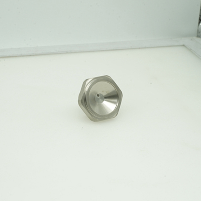
Deciding which components require extreme accuracy requires deep domain expertise. We can map tolerances based on operational criticality. Let us explore specific automotive systems to see where investment in precision yields actual returns.
Engine internals face extreme pressure, rapid movement, and intense friction. These environments demand absolute control over dimensional variances.
Examples: Cylinder heads, forged pistons, camshaft journals, and fuel injection components.
Required standards: This domain is where High Precision Car Parts become non-negotiable. Tolerances usually sit firmly in the ±0.01mm to ±0.005mm range. We need this extreme accuracy to maintain vital engine compression. It also guarantees correct oil clearances. Failing to meet these standards invites catastrophic mechanical failure.
These systems govern vehicle dynamics and passenger safety. While they are critical, they do not require the microscopic precision of engine internals. Instead, they require robust structural integrity.
Examples: Brake caliper mounts, lower control arm bushings, and steering knuckles.
Required standards: Tolerances here must guarantee perfect alignment and reliable fitment. They typically range from ±0.05mm to ±0.1mm. Imposing powertrain-level tolerances on suspension parts accomplishes nothing. Over-constraining these parts adds enormous manufacturing costs without improving vehicle safety or ride quality.
Many components exist solely for aesthetic appeal, basic structural mounting, or interior ergonomics. These parts rarely interact dynamically with moving mechanisms.
Examples: Dashboard display mounts, specialized wire brackets, and Custom Auto Hardware like aluminum shift knobs or pedal pads.
Required standards: Standard commercial tolerances are entirely sufficient here. Using ISO 2768-m (usually ±0.1mm to ±0.2mm) works perfectly. Instead of paying for unnecessary dimensional accuracy, redirect your budget. Focusing on superior surface finishes (Ra) yields a much better return on investment.
The gap between a pristine CAD model and the shop floor is wide. Bridging this gap requires strict adherence to Design for Manufacturing (DFM) principles. You must transition your prototype concepts into scalable production runs.
First, differentiate between standard and tight machining capabilities. Modern multi-axis milling centers easily hold standard tolerances around ±0.125mm. You can achieve this without drastically slowing down feed rates. However, demanding ±0.01mm usually requires costly secondary operations. Manufacturers often must implement centerless grinding, honing, or lapping to achieve these numbers reliably.
Specific geometries heavily compromise precision in CNC Machined Auto Parts. Engineers must actively avoid the following features:
Deep Holes: Drilling holes deeper than five times their diameter causes severe tool deflection. Vibration ruins concentricity and destroys tight tolerances.
Thin Walls: Walls thinner than 1.5mm are prone to warping. Machining forces and heat generation cause thin materials to flex away from the cutting tool.
Internal Radii: Specifying perfectly sharp internal corners is a costly mistake. It forces machinists to use tiny end mills. These fragile tools slow down production, break often, and compromise dimensional accuracy. Always specify the largest possible internal radius.
Finally, utilize GD&T best practices. Basic linear (+/-) tolerances are rarely sufficient for complex automotive assemblies. GD&T communicates functional intent. Using specific callouts like true position, surface flatness, and concentricity is highly preferred. It provides clear boundaries for manufacturers and prevents unnecessary part rejection.
Every zero added to a tolerance decimal point multiplies manufacturing costs. Engineers must understand this exponential cost curve. Stepping from a ±0.1mm requirement down to a ±0.01mm requirement drastically impacts the bottom line. It slows down machining times, accelerates tool wear, and requires specialized thermal setups.
Inspection and advanced metrology costs also soar. Tight tolerances require Coordinate Measuring Machines (CMM) for verification. If your specified tolerance is tighter than the shop's measurement capability, it cannot be verified. Unverifiable tolerances are functionally useless. They only serve to inflate quote prices.
Aggressive tolerances also crush acceptable yield rates. Tighter margins mean minor machining deviations turn raw material into scrap. Manufacturers directly transfer the financial burden of scrapped material back to the buyer. You will pay for every failed part on the shop floor.
The chart below outlines how tolerance selection directly impacts production factors.
Tolerance Range | Typical Application | Required Machining Process | Cost Multiplier | Scrap Risk Level |
|---|---|---|---|---|
±0.1mm to ±0.2mm | Brackets, interior mounts | Standard CNC Milling/Turning | 1.0x (Baseline) | Very Low |
±0.05mm | Suspension, chassis components | Precision CNC Machining | 1.5x - 2.0x | Low |
±0.01mm | Engine internals, pistons | CNC + Grinding/Honing | 3.0x - 5.0x | High |
±0.005mm | Fuel injectors, bearing journals | Lapping, Advanced Grinding | 8.0x+ | Very High |
Finding a reliable vendor goes beyond reviewing their equipment list. Possessing a brand-new 5-axis CNC machine does not guarantee precision. If the manufacturing floor lacks environmental temperature control, thermal fluctuations will destroy high-precision runs. You must evaluate their underlying quality management systems (QMS).
Look for specific certifications. Do they hold the IATF 16949 certification? This standard is specific to the automotive industry. It proves a much higher level of risk management than a standard ISO 9001 certification. Automotive supply chains require rigorous defect prevention methodologies.
Demand hard data regarding their process capability. A trustworthy manufacturer will gladly provide Statistical Process Control (SPC) data. Look for strong Cpk and Ppk values. A Cpk index of 1.33 or higher proves their machining process remains stable and predictable over long production runs. It means they can hit your tolerances reliably without relying on luck.
Finally, always mandate a First Article Inspection (FAI). Ensure they provide a comprehensive AS9102 or equivalent inspection report. Do this before greenlighting any high-volume Car Auto Parts production. Verifying their CMM readouts against your initial models is the only way to validate their claims.
True engineering excellence in automotive manufacturing relies on calculated efficiency. Applying tight tolerances exclusively where they solve functional problems is the hallmark of great design. For everything else, intelligent DFM principles should take priority. Rigid adherence to extreme accuracy across the board only sabotages your production timeline and budget.
Before launching your next project, follow these action-oriented next steps:
Conduct a comprehensive internal DFM review of your CAD models before distributing them for external quotes.
Replace basic linear tolerances with functional GD&T callouts to clarify design intent.
Audit potential suppliers by requesting recent Cpk capability reports and FAI documentation.
Revise material choices to account for thermal expansion in high-heat engine environments.
Do not let poor tolerance allocation derail your automotive build. Submit your 3D models and 2D drawings to an experienced manufacturing partner today. Request an expert design review to optimize your part tolerances for optimal cost, speed, and long-term performance.
A: General automotive components typically follow the ISO 2768 standard. Specifically, engineers rely on class 'm' (medium). This equates to an acceptable variance of around ±0.1mm for non-critical features. This standard provides excellent structural reliability while keeping machining costs and lead times highly efficient.
A: The most common culprit is applying blanket "tight tolerances" across the entire drawing. When you mandate ±0.01mm on non-mating surfaces, shops must use expensive secondary operations and slower feed rates. Loosening non-critical tolerances usually drops the final price significantly.
A: Yes. A very tight dimensional tolerance cannot be achieved or accurately measured if the surface finish (Ra) is too rough. Measurement probes will read the microscopic peaks and valleys of a rough surface, causing false out-of-tolerance readings. Precision dimensions require smooth surface finishes.
A: Metals expand when exposed to high heat. If you mate a tightly toleranced aluminum component to a steel part, the aluminum will expand faster. This causes binding, warping, or cracking at high temperatures. You must factor material thermal expansion coefficients into your initial tolerance designs.


